

Specifying underfloor heating: a guide for architects and self-builders
What a complete UFH specification states: heat losses, a 55C maximum flow temperature under Part L, BS EN 1264 surface limits, floor construction, zoning and controls, and a commissioning clause with BS 7593 water treatment.
Short answer: A complete UFH specification states the room-by-room heat loss, a design flow temperature of 55°C or below as Approved Document L requires for new and replacement systems, the pipe size and centres, the floor construction and finishes, the zoning and controls including boiler or heat pump interlock, and a commissioning clause covering pressure testing, water treatment to BS 7593 and balancing. Design outputs and surface temperature limits come from BS EN 1264, which caps occupied floor surfaces at 29°C.
Underfloor heating fails on site for specification reasons more often than product reasons: a floor build-up that was never coordinated with thresholds, a finish with no tog limit stated, a heat pump promised 45°C water flowing into a floor designed around 55°C. All of it is avoidable at drawing stage, and none of it is avoidable afterwards, because the pipe is the one layer of the building you cannot revisit.
This guide is for architects, self-builders and anyone writing a performance specification. It lists what the specification must pin down, the standards to cite, and the numbers that constrain the design, with a checklist you can lift. For how the regulations themselves are moving, see UFH under Part L and the Future Homes Standard.
What should a UFH specification include?
Ten items cover it. A specification that states all ten can go to any competent installer and come back as the same system:
- Heat loss per room, in watts and W/m², from a recognised calculation method.
- Heat source and design flow temperature, stated as a number, not a type.
- Pipe material and size, for example 16 x 2.0mm PERT-EVOH barrier pipe, oxygen tight to DIN 4726.
- Pipe centres per room, including any perimeter bands along glazing.
- Floor construction per level, screed type and depth, overlay board, or joisted system, with the total build-up height.
- Floor finishes and their limits, tile, timber or carpet, with maximum tog values stated.
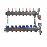
- Zoning schedule, which rooms share a thermostat and where manifolds sit.
- Controls, thermostat type, wiring centre, interlock with the heat source.
- Electrical and gas scope, final connections by a qualified electrician to BS 7671, boiler work by a Gas Safe engineer, heat pumps by an MCS installer where grants are in play.
- Commissioning and handover, pressure test, water treatment, balancing and documents.
Manifold positions deserve drawing time, not a note: central positions shorten tails, and every port needs access for life.
Which standards and regulations apply?
Cite them by name and let them do the work:
- BS EN 1264 for the design of water-based surface heating: outputs, surface temperature limits and test methods.
- Approved Document L (England, 2021 edition) for energy performance: new and replacement wet systems sized to a maximum 55°C flow temperature, zoned time and temperature control, and commissioning with the notice given to building control.
- BS 7593:2019 for water treatment: clean, inhibit, in-line filter, annual checks.
- BS 7671 and Part P for every electrical connection, including wiring centres, actuators and thermostats.
- MCS standards for heat pump installations, which also gate grant eligibility.
Our guide to BS EN 1264 and BS 7671 for UFH unpacks the two standards specifiers lean on most. Scotland, Wales and Northern Ireland set their own building regulations, so check the national documents where the project sits.
What design limits should the specification state?
These are the numbers the design must sit inside. Quoting them in the specification stops value engineering from quietly breaking the design later.
| Parameter | Limit | Source |
|---|---|---|
| Floor surface, occupied areas | 29°C max | BS EN 1264 |
| Floor surface, bathrooms | 33°C max | BS EN 1264 |
| Floor surface, perimeter zones | 35°C max | BS EN 1264 |
| Design flow temperature, new and replacement systems | 55°C max | Approved Document L 2021 |
| Supply temperature into cement screed | 55°C max | EN 1264 guidance |
| Loop length, 16mm pipe | about 100m | design guidance |
| Water velocity in loops | about 1m/s max | design guidance |
The 29°C surface limit means roughly 100W/m² is the ceiling on output in a 20°C room. Where a room's heat loss exceeds what the floor can give at the design flow temperature, the specification must say what closes the gap: better fabric, closer pipe centres, or supplementary heat. Discovering it at commissioning is the expensive version. Start from a proper heat loss calculation; see UFH heat loss calculations.
How should the floor construction be specified?
Name the system per level, with its build-up height, and coordinate that height with thresholds, stairs and door openings at drawing stage.
- Screeded ground floors: insulation, pipe on clip rail or castellated panels, then sand-cement or liquid screed. Highest output and thermal mass, deepest build-up, and a drying period the programme must hold.
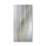
- Low-profile overlay: routed boards such as MaxHeatPanel, MaxHeatDeck or the 15mm MaxHeatFix system over an existing slab, for refurbishment and storeys where depth is tight. Fixed pipe centres, so the output must be checked against the room, not assumed.
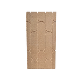
- Joisted floors: spreader plates or grooved chipboard such as MaxHeatChip between or over joists, specified with the deck and finish above.
State the finish and its limit in the same clause: timber and laminate makers publish maximum surface temperatures and carpet systems a maximum tog, and the UFH design must respect both. Build-up heights for each system are tabulated in UFH floor build-up heights.
How should zoning and controls be written?
Approved Document L expects each heating zone to have independent time and temperature control, with the controls providing interlock so the heat source cannot run against no demand. For UFH that translates to:
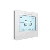
- A thermostat per zone, wired or wireless, with the zoning schedule deciding how many. Rooms with different uses get different zones; see how many UFH zones.
- A wiring centre per manifold, such as the Heatmiser UH8, combining zone demands into pump and heat source enable signals.
- A stated weather or load compensation strategy where the heat source offers one, and floor probes where finishes need a surface limit enforced.
- For heat pumps: design the floor for the lowest workable flow temperature, state it, and specify the non-mixing or mixing arrangement at the manifold accordingly.
What should the commissioning clause require?
Make the records deliverables, not favours. The clause should require:
- Pressure test of every loop before covering, held and recorded, with the result signed.
- Photographic record of the laid pipe in every room before screed or deck.
- Water treatment to BS 7593: clean, flush and inhibitor dose, recorded, as Approved Document L's commissioning guidance expects.
- Balancing of loops to design flow rates at the manifold flow meters.
- Controls demonstration and handover file: settings, zone schedule, manifold labelling and the documents above, with the commissioning notice to building control.
Our UFH commissioning guide expands each step into a method.
Supply only, or supply and design?
MaxHeatUFH supplies trade and self-build projects UK-wide, with next working day delivery on orders placed by 12pm Monday to Friday and trade accounts with trade prices. We do not install; installation enquiries are passed to vetted approved installers. For early-stage design, you can design your UFH system yourself in MaxHeatUFH ProLoop and get a quick UFH design, with the circuits laid out from the manifold you place and a fully priced kit, in 3 minutes, and a full loop design can be ordered later at £0.40 per heated m². The design fee you paid is taken off the kit price when you order the kit linked to that design. Specification questions can go to sales@maxheatufh.com.
Design your UFH system yourself in 3 minutes with MaxHeatUFH ProLoop and get an instant quick design and quote. Start your design
Frequently asked questions
What flow temperature should I specify for underfloor heating?
55°C is the ceiling Approved Document L sets for new and replacement systems; specify lower where the heat source allows it, since heat pumps perform better the cooler the floor can run. State the number in the specification rather than leaving it to the installer.
Can I write a performance spec and leave the loop design to the supplier?
Yes, and it is the usual route: state heat losses, flow temperature, floor construction, finishes and the standards, and have the supplier's design demonstrate compliance. Keep the design limits in the spec so compliance is checkable.
What pipe should a specification name?
Barrier pipe, stated by material, size and standard: for example 16 x 2.0mm PERT-EVOH, oxygen tight to DIN 4726, or a multilayer PERT-AL-PERT where the aluminium layer is wanted. Oxygen tightness is the non-negotiable part.
How do I coordinate UFH with the build programme?
Pipe laying follows first fix and insulation, screed follows the pressure test, and drying time sits on the critical path before finishes. Our guide to the new build UFH sequence maps the trades in order.
Does underfloor heating need its own electrical certificate?
The controls wiring is notifiable fixed wiring like any other: a qualified electrician connects wiring centres, thermostats and pumps to BS 7671, with Part P applying in dwellings, and certification forms part of the handover file.
Who signs off a heat pump UFH system for grants?
Grant-funded heat pump installations are carried out by MCS installers, and the UFH design must match the flow temperature the heat pump is commissioned to. On VAT, be clear with clients: 0% VAT on energy-saving materials applies only where a qualifying installer supplies and installs qualifying measures, so kit bought supply-only from a merchant, including MaxHeatUFH, includes 20% VAT. See UFH grants and VAT for the current position.
Sources: BEAMA Part L 2021 heating guidance
Products in this guide
Watch how each part works and how to fit it, and download its data sheet and install manual.




Every data sheet and manual: Product Library · All videos: MaxHeatUFH on YouTube
Design it in MaxHeatUFH ProLoop
Add your rooms, choose screed, overlay, joisted or electric, and get a free quick design and full kit list with prices.