



Fitting the floor probe for electric underfloor heating
Where the floor probe goes with an electric heating mat, how to run the conduit so the probe can be replaced, why you should always bury a spare, and how to test or swap a failed probe without lifting tiles.
Short answer: Fit the floor probe in a flexible conduit, run 200 to 300mm into the heated floor, centrally between two heating cable runs and never touching or crossing them. Seal the end of the conduit with tape so adhesive cannot get in, keep any bend gentle, and fit a second, spare probe in its own conduit while the floor is open; it adds very little to the job and saves ripping up tiles if the first probe ever fails. A qualified electrician makes the final connection at the thermostat under Part P of the Building Regulations and BS 7671.
The floor probe is a small thermistor on the end of a long lead, and it is the most underrated part of an electric underfloor heating installation. It tells the thermostat the actual floor temperature, which is what lets the system hold the tiles at a comfortable level, protect the adhesive and the floor covering from overheating, and keep the surface within the contact temperature limit that BS 7671 expects for heated floors.
It is also the one component that gets buried with the heating mat and cannot be inspected later. Ten minutes of care when you fit it, and one spare probe left in the floor, remove almost every control problem the system could give you in the next twenty years. This guide covers where the probe goes, how to fit it, how to test it, and what to do if one fails under a finished floor.
Where should the floor probe go?
Centrally between two runs of heating cable, inside the heated area. One manufacturer's installation guide for electric mats says the sensor tube should be laid so the sensor sits between two heating wires, not across them and not over any pipes below the floor, and another manufacturer's instructions for its sensor conduit say the same thing: the sensor should sit in the middle of the cable-to-cable distance.
Get these three things right:
- Distance into the floor. Run the probe roughly 200 to 300mm into the heated area, so it reads the heated floor and not the cold margin by the wall.
- Centred between cables. Midway between two cable runs. Against a cable it reads hot and the thermostat cuts the floor back too early; too far from the cables it reads cold and the floor can overheat the adhesive.
- Away from other heat. Not above hot water pipes, not next to the cold tail joint, and not in a patch of floor that gets direct sun through glazing.
The probe position should be directly below the thermostat position where practical, so the conduit runs straight down the wall and out into the floor. Mark the probe's position on the installation plan; you will be glad of it years later.
How do you fit the probe conduit?
Always put the probe in a conduit rather than burying it bare in the adhesive. The point of the conduit is that the probe can be pulled out and a replacement pushed in without touching the floor.
- Chase or channel the route. Cut a shallow channel in the insulation board or subfloor for the conduit so it sits flush and does not create a hump under the tiles.
- Run flexible conduit from the thermostat back box down the wall and 200 to 300mm into the floor, ending centrally between two cable runs. The first of those manufacturers specifies a 10mm flexible tube for the job.
- Keep bends gentle. The second states a minimum bend radius of 50mm for its sensor conduit, and the wall-to-floor bend is the one to watch. A tight bend will stop you pulling the probe out later, which defeats the purpose.
- Seal the floor end. Tape the end of the conduit closed so tile adhesive cannot enter and set around the probe.
- Slide the probe in to the end and check it moves freely before any adhesive goes down. If it will not pull back now, fix the conduit run now.
The 3m lead on a standard probe, such as our 10K floor probe, is enough for a normal thermostat height; the lead can usually be shortened but never extended casually, so plan the route before cutting anything and follow the thermostat maker's instructions.
Should you fit a spare floor probe?
Yes, every time. While the floor is open, laying a second probe in its own sealed conduit, a short distance from the first, costs a spare probe, a metre of conduit and five minutes. Coil the spare lead in the thermostat back box, label it, and record both probe positions.
If the working probe ever fails, the electrician swaps the thermostat's sensor wires to the spare and the system is running again the same day. Without a spare, the options are pulling a replacement through the conduit, which works only if the conduit was laid well, or running the thermostat on air sensing, which loses the floor temperature limit. Our guide to floor probes versus air sensing explains what you give up.
Which probe does your thermostat need?
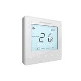
The thermostat and probe must match electrically. A probe is a thermistor named for its nominal resistance: the Heatmiser neoStat-e, for example, ships with a 3m floor sensor and is compatible with 10K, 12K and 15K probes, selectable in its settings. Fit the probe supplied with the thermostat, or a replacement of the same rating, and set the thermostat's sensor type to match.
Three probe decisions worth knowing about:
- Sensor mode. Electric floor thermostats such as the neoStat-e can control on floor temperature alone or on air temperature with the probe acting as a floor limit. For tiled and stone floors over our mats, floor sensing or air-plus-floor-limit keeps the surface and the adhesive protected. See setting up the neoStat-e for electric UFH.
- Housing. A sensor probe housing gives the probe tip a protective sleeve in the floor and makes replacement easier.
- Lead routing. Keep the probe lead separated from mains cables where the manufacturer requires it, and never run it alongside the heating cable's cold tail in the same conduit.
How do you test a floor probe?
With the power isolated, disconnect the probe wires at the thermostat and measure the resistance across them with a digital multimeter. A healthy thermistor gives a steady resistance that matches the thermostat maker's resistance table for the current floor temperature, and the reading falls as the sensor warms; warming the probe tip in your hand and watching the resistance drop is the standard functional check. A reading of zero means a short circuit; an open circuit or wildly unstable reading means a broken probe or lead.
Test at three points during installation, exactly as you test the heating mat itself: before the mat and probe go down, after the adhesive is applied, and before the thermostat is fitted. Record the readings alongside the mat's continuity and insulation tests; our guide to testing electric UFH during installation has the full sequence. Always isolate the circuit before measuring resistance.
What if the probe fails under a tiled floor?
Work through the options in this order:
- Confirm it is the probe. Measure its resistance and compare against the maker's table. Many "probe faults" turn out to be a loose terminal at the thermostat, and many thermostat error codes name the floor sensor directly. Our fault finding guide covers the error codes.
- Switch to the spare probe if one was fitted. This is the five-minute fix.
- Pull a replacement through the conduit. Tape the new probe lead to the old one and draw it through as you withdraw the old probe. This works when the conduit was laid with gentle bends and a sealed end.
- Fall back to air sensing. Most electric UFH thermostats can run on their built-in air sensor if the floor probe is unusable. You lose the floor limit, so set conservative temperatures, and treat it as a stopgap for a floor that will be refurbished one day.
What you should not do is lift tiles on a guess. The probe is cheap; the floor is not, and a well-laid conduit or a spare probe means you never face that choice.
A qualified electrician must make the final connection of the heating and the probe at the thermostat, and the circuit must be RCD protected, tested and certified under Part P of the Building Regulations and BS 7671.
Free design tool: planning water underfloor heating elsewhere in the house? Design your UFH system yourself in 3 minutes with MaxHeatUFH ProLoop and get an instant quick design and quote. Start your design
Frequently asked questions
Where should the floor probe be placed with an electric mat?
In a sealed flexible conduit, 200 to 300mm into the heated area, centrally between two heating cable runs, never touching or crossing a cable, and away from pipes, the cold tail joint and direct sun.
Does the floor probe have to be in a conduit?
Fit one every time. Manufacturers' instructions specify a flexible tube with the end sealed against adhesive, and the conduit is what lets a failed probe be replaced without lifting the floor.
Can I fit two floor probes?
Yes, and you should. Only one connects to the thermostat; the second sits in its own conduit as a spare, with its lead coiled in the thermostat back box.
What resistance should a floor probe read?
It depends on the probe rating and the floor temperature: check the thermostat maker's resistance table. The reading should be steady and should fall as the probe warms. Zero means a short; no reading means a broken probe or lead.
Can the probe lead be shortened or extended?
Shortening is usually fine. Extending should only be done as the thermostat manufacturer allows, with the right cable and separation from mains wiring. Check the instructions before altering anything.
Can I run electric underfloor heating without a floor probe?
Most thermostats will run on air sensing, but you lose the floor temperature limit that protects the adhesive, the floor finish and barefoot comfort. For heating buried in a tiled floor, floor sensing or an air mode with a floor limit is the right setup.
Who connects the probe to the thermostat?
A qualified electrician, as part of making the final connection of the system. The heating circuit must be protected by a 30mA RCD and the work certified under Part P and BS 7671.
Sources: IET Wiring Matters: floor and ceiling heating systems (BS 7671 Section 753)
Products in this guide
Watch how each part works and how to fit it, and download its data sheet and install manual.



Every data sheet and manual: Product Library · All videos: MaxHeatUFH on YouTube

Design it in MaxHeatUFH ProLoop
Add your rooms, choose screed, overlay, joisted or electric, and get a free quick design and full kit list with prices.


