



Boiler interlock and pump control for underfloor heating wiring centres
What boiler interlock means for underfloor heating, how a wiring centre switches the boiler and UFH pump, the UH8 heat-enable and pump terminals, and when you need an extra relay.
Short answer: Boiler interlock means the controls are wired so that when no room needs heat, the boiler and the pump both switch off. On underfloor heating, the wiring centre does this: when any room thermostat calls, it opens that zone's actuator, runs the UFH pump and closes a heat-enable contact to fire the boiler or heat pump. When every thermostat is satisfied, the pump and heat source drop out. On a Heatmiser UH8, the heat enable is a volt-free contact (LS to LR) and the pump has its own 230V output, within a 3A relay and 5A total board limit.
Most UFH problems that look like a faulty boiler are really wiring problems. A pump on a permanent live, a boiler that is always being called, or a zone valve end switch that never closes will all make the system waste energy or not heat at all. Getting the interlock right is what turns a manifold full of actuators into a heating system that switches itself on and off.
This guide explains what boiler interlock is, how a wiring centre provides it, how the pump output and heat-enable contact work, when you need an extra relay, and how UFH ties in with radiator zones and heat pumps. For a terminal-by-terminal walk-through, see our Heatmiser UH4 and UH8 wiring guide. All of this work is for a qualified electrician, and work on the boiler itself is for a Gas Safe engineer.
What is boiler interlock?
Boiler interlock is a way of wiring the controls, not a box you buy. BEAMA's Part L heating controls guidance defines it as controls wired so that when there is no demand for space heating or hot water, the boiler and pump are switched off. It adds that thermostatic radiator valves alone do not provide interlock.
BEAMA's underfloor heating controls guide applies the same idea to UFH: when there is no demand for heat from the UFH system, the heat source and the circulating pump should be switched off. It says the interlock is provided by switching the boiler on and off through the main heating system wiring centre.
The rules now sit in Approved Document L, Volume 1: Dwellings. BEAMA notes that the Domestic Building Services Compliance Guide no longer applies in England, because its guidance and minimum standards have been taken into the Approved Document.
Interlock is one part of a set of minimum controls. BEAMA's UFH controls guide also says:
- Room control: each room must have its own room thermostat or sensor. Rooms with a similar use, such as a kitchen and utility, may share one.
- Time control: one time controller may serve a heated area of up to 150m². Each extra zone needs its own time controller.
- High mass floors: for screeds over 65mm, a night setback should let the room cool by only around 3°C overnight.
How does a UFH wiring centre provide interlock?
It collects every room thermostat in one place and turns their calls into two outputs: one for the heat source and one for the pump. The sequence on a call for heat goes like this:
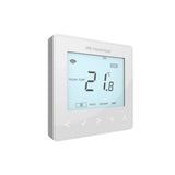
- Thermostat calls. A room drops below its set point and its thermostat sends 230V to the wiring centre.
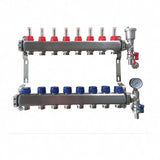
- Actuator opens. The wiring centre powers that zone's thermal actuator on the manifold.
- Pump runs. Because a UFH zone is calling, the pump output switches on.
- Heat source fires. The heat-enable contact closes and the boiler or heat pump starts.
- Last zone satisfied. When no zone is calling, the actuators close and the pump and heat-enable outputs drop out together.
That last step is the interlock. If the pump or boiler is wired to a permanent live instead of the wiring centre outputs, the system has no interlock, however many thermostats you fit. Our guide to the UFH wiring centre explains each output in full.
What do the UH8 boiler and pump terminals do?
The Heatmiser UH8 manual sets out two separate outputs for the heat source and the pump, plus a valve output for systems with a zone valve.
| Output | Terminals | What it does |
|---|---|---|
| Heat enable (boiler) | LS, E, LR | Volt-free: LS is connected to LR on a call for heat |
| UFH pump | L, E, N | 230V to the manifold pump when a UFH zone calls |
| UFH valve | L, E, N, Gr, Or | Powers a zone valve; Gr and Or take the valve end switch |
| Mains in | L, N, E | 230V supply, fused at 5A |
The manual gives a relay load of 3A resistive and a total board load of 5A resistive, with a 5A 20mm anti-surge fuse protecting the 230V zone and pump outputs. The UH8 and the four-zone UH4 have the same board and relay limits.
Should the boiler be switched with a volt-free or switched live connection?
Follow the boiler or heat pump manual, because the UH8 heat-enable contact can do either. It is volt-free, which means it is just a switch between LS and LR. What you feed into LS decides what comes out of LR.
- Volt-free input on the heat source: wire LS and LR across the boiler's room thermostat or demand terminals, with no mains on the contact.
- Switched live input: feed a permanent live into LS, and LR becomes the switched live to the boiler or to a zone valve circuit.
Never put mains onto a heat source input that expects a low-voltage, volt-free contact. Some boilers have a 24V or other low-voltage thermostat loop, and 230V will damage the board. If you are not sure which type you have, that is the point to stop and read the manual.
On a combi boiler, the wiring centre's heat-enable contact usually goes to the boiler's external control or room thermostat terminals. Our guide to connecting UFH to a combi boiler covers the pipework side.
How should the UFH pump be wired?
Wire the pump to the wiring centre's pump output, not to a permanent supply, so it only runs when a UFH zone is calling. The UH8 manual also recommends feeding the pump through a high limit thermostat on the manifold. That protects the floor if the manifold's own temperature control fails.
BEAMA's guide explains why: a high limit thermostat prevents water above 60°C entering the UFH loops if other water temperature controls fail. It applies wherever the heat source can make water hotter than 60°C, which covers most boilers. With a boiler, BEAMA also says a blending device must be fitted so the floor gets water at its design temperature, typically 40 to 55°C.
The UH8 manual does not document a pump overrun on the UFH pump output. If your boiler needs a pump overrun, that is done by the boiler's own pump control, so check the boiler manual.
When do I need a separate pump relay?
Add a relay when the wiring centre output is not rated for the load, or when more than one control needs to switch the same pump or heat source. Common cases:
- The load is over the board limit. The UH8 relay rating is 3A resistive and the whole board is 5A. A large pump or a pump plus other loads on one output can need an external relay or contactor sized by the electrician.
- Two wiring centres, one pump or boiler. On a large house with two manifolds, each wiring centre's heat-enable contact can be wired so that either one can call the heat source, without linking the two boards' mains supplies together.
- The heat source needs a different signal. A heat pump or boiler that only accepts a low-voltage input may need an interface relay between it and other controls.
Keep the relay ratings in mind. The UH8 figures are for resistive loads. Motors such as pumps, and the inrush of many actuators at once, are why you should not design to the last amp.
How does UFH interlock work with radiators and zone valves?
Each heating circuit calls the boiler on its own, and the boiler fires if any of them calls. On a system with radiators upstairs and UFH downstairs, the UFH side goes through the wiring centre and a 2-port zone valve, and the radiator side has its own programmer, room thermostat and zone valve.
The zone valve end switch is part of the interlock. When the valve is fully open, its end switch closes and passes the call to the boiler. On the UH8, the valve's auxiliary wires go to the Gr and Or terminals. The manual says to link Gr and Or if no valve end switch is fitted. Leave that link out with no valve fitted and the boiler will never be told to fire. See our guide to how UFH actuators and zone valves work.
The UH8 also has a radiator option on zone 8. In RAD mode, a zone 8 call energises the radiator zone valve and the boiler, but not the UFH pump or valve. In UFH mode, zone 8 behaves like the other underfloor zones.
What does interlock look like with a heat pump?
The principle is the same: the wiring centre's heat-enable contact tells the heat pump there is demand, and the pump output runs the UFH circulator when a zone calls. The detail depends on the heat pump. Many have their own demand input and their own primary pump, and some control the UFH pump speed directly.
Wire the heat-enable contact to the input the heat pump manual names for an external thermostat or demand signal. On heat pump jobs, the MCS installer designs the controls, and getting the interlock wrong can stop the system meeting its design. Our guide to UFH with a heat pump covers the hydraulic side.
Design your UFH system yourself in 3 minutes with MaxHeatUFH ProLoop and get an instant quick design and quote. Start your design
Frequently asked questions
Is boiler interlock a legal requirement?
Boiler interlock is one of the minimum heating controls set out in Approved Document L for England. BEAMA's guidance summarises it as the boiler and pump switching off when there is no demand for heating or hot water.
Do TRVs give boiler interlock?
No. BEAMA's guidance states that thermostatic radiator valves alone do not provide interlock. A room thermostat or wiring centre must be able to switch the boiler off.
Is the UH8 boiler output volt-free?
Yes. The Heatmiser UH8 manual describes it as a volt-free output: terminal LS is connected to LR on a call for heat.
Why does my boiler not fire when the UFH calls?
Common causes are a missing link between Gr and Or when no zone valve end switch is fitted, the heat-enable contact wired to the wrong boiler terminals, or a high limit thermostat that has tripped. An electrician can check each with a meter.
Can the UFH pump run all the time?
It should not. Wire it to the wiring centre's pump output so it only runs when a UFH zone is calling. BEAMA's guide says the pump and heat source should be switched off when there is no UFH demand.
How many actuators can one UH8 zone run?
Up to six actuators per zone, within the 5A total board limit. A large open-plan room with several loops can run them all from one thermostat.
Can I wire the wiring centre myself?
The wiring centre, pump and boiler connections are mains electrical work, so use a qualified electrician. Any work on a gas boiler itself must be done by a Gas Safe registered engineer.
Sources: BEAMA Part L 2022 heating controls guidance, BEAMA underfloor heating controls guide, Heatmiser UH8 manual
Products in this guide
Watch how each part works and how to fit it, and download its data sheet and install manual.



Every data sheet and manual: Product Library · All videos: MaxHeatUFH on YouTube

Design it in MaxHeatUFH ProLoop
Add your rooms, choose screed, overlay, joisted or electric, and get a free quick design and full kit list with prices.


