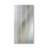


Underfloor heating design and layout: what a loop plan shows and how to read it
What a water underfloor heating design should contain, from room heat loss and output checks to the loop schedule, manifold position and floor section, and how to read a loop plan before you build.
Short answer: An underfloor heating design is a drawing and a set of tables that show where every pipe loop runs, how far apart the pipes are, where the manifold goes, how long each loop is, and what heat output each room gets at your flow temperature. A good design starts from a room-by-room heat loss and checks the floor can meet it within the surface temperature limits in BS EN 1264. You do need one for any water system bigger than a single small room, and for a heat pump it is part of the MCS design work.
A loop plan is the instruction sheet for the floor. The installer follows it to lay each pipe in the right pattern and at the right spacing, cut the coils in the right lengths, and connect each loop to the right manifold port. Once the screed or boards are down, you cannot change any of it.
This guide explains what a UFH design should contain, how to read the drawing and the loop schedule, how to check it is sound, and when a quick design is enough before you order a full one.
Do I need an underfloor heating design?
Yes, for any water system that covers more than one small room. The design sets the loop lengths, pipe spacing, manifold size and flow temperature, and those decide whether the rooms reach temperature.
Without a design you are guessing at three things that cannot be changed later: whether the floor gives enough heat, whether the loops can be balanced, and whether the manifold is in the right place. Building industry guidance says the UFH design should be ready by the first fix stage, and that the loop layout should take account of anything that will go through the floor, such as soil pipes and service ducts.
For a heat pump, the MCS heat pump design standard (MIS 3005-D) requires a building heat load calculation to BS EN 12831-1, and the customer must be given each room's heat loss in W/m² before installation. Grant-funded heat pump jobs need that work done by an MCS installer.
A single electric mat in a bathroom does not need a drawn loop plan, but it still needs the heated area worked out properly. See how to install an electric underfloor heating mat.
What should an underfloor heating design include?
A complete water UFH design should include the pipe layout, the heat output for each room, the loop schedule and the manifold details. Here is what to look for.
| Part of the design | What it tells you |
|---|---|
| Room heat loss | Watts and W/m² each room needs at its design temperature |
| Output table | Room temperature, flow temperature, floor finish and the output the floor gives |
| Pipe layout drawing | The route of every loop, room by room |
| Pipe centres | Spacing for each area, including any tighter edge band |
| Loop schedule | Length, area and flow rate of each loop, and which manifold port it uses |
| Manifold position and size | Where it hangs and how many ports it needs |
| Coil cut table | Which loops come from which pipe coil |
| Floor section | The build-up: insulation, pipe, screed or board, finish |
| Heated and total area | Heated area for pipe, total area for boards and insulation |
| Controls | Zones, thermostats, actuators and wiring centre |
Not every design shows all of these on one sheet, but if the heat loss, output check or loop schedule is missing, ask for it. They are the parts that prove the system will work.
How do I read a UFH loop plan?
Start at the manifold and follow each loop out and back. Each loop is usually drawn in its own colour or numbered, and the same number appears in the loop schedule and on the manifold port.
- Find the manifold. It is marked on the plan, often in a cupboard, utility or under the stairs. Ports are numbered from one end.
- Follow the feed runs. The flow and return leave the manifold side by side and travel to the room. These metres count in the loop length but give little useful heat in that room.
- Read the pattern in the room. Serpentine loops snake back and forth. Spiral (also called counter-flow or snail) loops run in towards the centre and back out between the outgoing runs, which evens out the floor temperature.
- Check the spacing. The plan or a key gives the pipe centres, such as 150mm, and shows any tighter band by outside walls or glazing.
- Check the schedule. Each loop has a length, an area and a flow rate. The installer sets the flow meter on each port to that rate when balancing the loops.
- Look for the notes. Conduit at doorways, expansion joints, zones where pipes must not go, and the position of floor probes or thermostats.
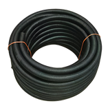
Pipe that passes through walls, doorways, expansion or day joints, or rises out of the floor at the manifold is usually sleeved. One maker specifies a 400mm length of conduit at each of those points. Our pipe conduit for 16mm pipe comes in 25m coils.
How does a designer check the floor will heat the room?
The designer compares each room's heat loss per m² with what the floor can give out at the chosen flow temperature, floor finish and pipe spacing. If the output is lower than the loss, the design changes before anything is ordered.
Pipe maker handbooks set out the steps in this order:
- Work out the heat load of each room to BS EN 12831.
- Work out the heat output each room needs, plus any allowance.
- Divide by the heated floor area and check it against the floor's limit.
- Set the flow temperature.
- Work out the water flow rate, then split it between the loops.
- Work out each loop's length and pressure loss, and balance the flows.
The limit comes from the floor surface temperature that BS EN 1264 allows:
| Area | Maximum floor surface |
|---|---|
| Occupied areas | 29°C |
| Edge zone, up to 1m wide | 35°C |
| Bathrooms | Room temperature + 9°C, so 33°C at 24°C |
The floor finish matters too. The same handbook designs living rooms with a floor covering resistance of 0.10m²K/W and bathrooms at 0, with anything up to 0.15m²K/W agreed separately. If a room needs more heat than the floor can give, the options are closer pipe, a lower-resistance finish, more insulation in the room or a second heat source. Our guide to heat loss and UFH output explains the sums.
What loop lengths and spacing should a design use?
Most UK designs on 16mm pipe keep each loop to about 100m and use 100 to 200mm centres. Longer loops are harder to balance and need more pump effort.
One pipe maker's handbook recommends circuits no longer than 100m and a pressure loss across each circuit of no more than 250 mbar. Another maker's solid floor guide gives a 100m maximum circuit length with 22m² per loop at 200mm centres and 11m² at 100mm. For the spacing choice itself, see pipe centres: 100, 150 or 200mm.
A design should also keep loops in one room where possible. One loop serving two rooms with different thermostats cannot be controlled properly. Large rooms get two or more loops, each on its own port with its own actuator, all switched by the one room thermostat.
Where should the manifold go?
As close to the middle of the rooms it serves as you can manage, on a wall where it can be reached for filling, venting and balancing. A central manifold keeps feed runs short, which leaves more of each loop for heating the room.
Check the space before the design is fixed. The manifold needs room below it for the pipes to rise out of the floor and room to one side for the pump and mixing set if the heat source runs hotter than the floor. Large or multi-storey houses often need more than one manifold, and trade guidance says each manifold's position needs careful thought so every room is served.
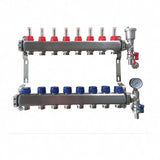
A design should show the port count. One loop needs one port, so a plan with nine loops needs at least a 9-port manifold, such as the Dualmix stainless steel manifold, which comes in 2 to 12 ports.
What should the floor section and notes show?
The floor section shows each layer from the slab or joists up to the finish, with thicknesses. It lets the builder check floor levels, door thresholds and the insulation, and lets the screed or board installer check their part.
- Insulation below the pipes: one handbook gives minimum resistances of 0.75m²K/W over a heated room, 1.25m²K/W over an unheated room or the ground, and 2.00m²K/W over outside air.
- Edge strip: a compressible strip around the walls and fixed objects, such as our edge insulation roll.
- Screed depth: sand and cement screed is at least 65mm for domestic use. Flowing screeds follow the screed supplier's figure.
- Expansion joints: in stone and tiled screeds, BS EN 1264-4 recommends a joint about every 40m², with no side over 8m.
Read the notes as carefully as the drawing. They tell the installer where pipes must not go, where joints are and where sensors sit. See insulation under underfloor heating for the insulation rules in more detail.
Design your UFH system yourself in 3 minutes with MaxHeatUFH ProLoop and get an instant quick design and quote. When you are ready to build, order a full loop design for £0.40 per heated m². The design fee you paid is taken off the kit price when you order the kit linked to that design. Start your design
Frequently asked questions
What is the difference between a quick design and a full loop design?
In a quick design you set out the rooms and place the manifold, and ProLoop lays out the circuits so you can see the kit and the price. A full loop design adds the drawn pipe route for every loop, the loop schedule with lengths and flow rates, and the coil cut table the installer works from.
Who should do the heat loss calculation?
The designer or installer, using BS EN 12831. For a heat pump, MCS requires it, and the installer must give you each room's heat loss in W/m² before the work starts.
Can I lay the pipe without a drawing?
For one small room on a short loop, an experienced installer can. For a whole floor you should not, because loop lengths, manifold ports and balancing all depend on the plan.
Why are some loops on the plan tighter near the windows?
That is an edge or perimeter band. BS EN 1264 allows the floor surface to run up to 35°C in a band up to 1m wide, so closer pipe there puts extra heat where the room loses most.
What happens if the design changes on site?
Small changes, such as moving a kitchen unit, can be handled by re-routing one loop. Any change that moves the manifold or adds a room should go back to the designer, because loop lengths and flow rates change.
Does the design tell me which floor finish to use?
It should state the finish it was designed for, because output depends on it. If you change from tiles to carpet, ask for the output to be rechecked.
How many loops can one manifold have?
Our Dualmix manifold comes in 2 to 12 ports. Large homes often use more than one manifold so the feed runs stay short.
Sources: MCS MIS 3005-D heat pump design standard, PBC Today: UFH systems and building control, BEAMA guide to low profile UFH, and manufacturers' installation guidance to BS EN 1264
Products in this guide
Watch how each part works and how to fit it, and download its data sheet and install manual.




Every data sheet and manual: Product Library · All videos: MaxHeatUFH on YouTube

Design it in MaxHeatUFH ProLoop
Add your rooms, choose screed, overlay, joisted or electric, and get a free quick design and full kit list with prices.